This page describes an overview of Autoware based on the Version 2.0 design and implementation. For more details, you may refer to the design rules and the specification of Autoware.
本页描述了基于2.0版本设计和实现的 Autoware 的概述。 更多的细节,你可以参考设计规则和 Autoware 的规范。
1. 传感器
Autoware supports Camera, LiDAR, IMU, and GPS as primary sensors. The following are examples of those already verified with Autoware through field testing. Technically speaking, if not verified, almost all types of Camera, LiDAR, IMU, and GPS should be available for Autoware, as far as sensor driver software is provided.
Autoware 支持相机,激光雷达,IMU 和 GPS 作为主要传感器。 下面是已经通过 Autoware 实地测试验证的例子。 从技术上讲,如果没有经过验证,几乎所有类型的相机,激光雷达,IMU,和 GPS 都应该可以在 Autoware 上使用,只要传感器驱动软件已经提供。
1.1. 相机
- PointGrey (FLIR) Grasshopper 3 (USB/GigE) [link]
- PointGrey (FLIR) Flea 2/3 (USB/GigE) [link]
- PointGrey (FLIR) Blackfly (USB3/GigE) [link]
- Baumer VLG-22C (USB3/GigE) [link]
- Baumer VCXU-24C (USB3/GigE) [link]
- Allied Vision Camera Mako G-319C (PoE GigE) [link]
- Generic UVC Webcam (USB2/3)
支持多个摄像机传感器,但是它们应该根据不同的目的分别配置。 请为每个实例使用名称空间或名称来验证 ROS 文档。 分离每个相机的目的,如目标检测和交通信号灯识别。 从本质上讲,Autoware 不支持将多个图像连接到单个大图像中。
1.2. 激光雷达
- VELODYNE HDL-64E (S1/S2/S3) [link]
- VELODYNE HDL-32E [link]
- VELODYNE VLP-32C [link]
- VELODYNE VLP-16 [link]
- VELODYNE VLP-16 Lite [link]
- VELODYNE VLP-16 Hi-Res [link]
- HOKUYO YVT-35LX (3D-URG) [link]
- HOKUYO UTM-30LX (TOP-URG) [link]
- SICK LMS511 [link]
- PIONEER 3D LiDAR (yet to be released) [link]
You may combine multiple units of the above LiDAR scanners through TF, providing rich fused pointcloud data for more precise object detection, tracking, and localization. Please check Velodyne's documentation on how to use multiple sensors in the same network.
您可以通过 TF 组合上述 LiDAR 扫描仪的多个单元,提供丰富的融合点云数据,以实现更精确的目标检测、跟踪和定位。 请查看 Velodyne 的文档,了解如何在同一个网络中使用多个传感器。
1.3. 毫米波雷达
- Delphi ESR [link]
自动检测主要是基于激光雷达扫描仪。 毫波雷达驱动程序也可用于远距离目标跟踪。 然而,它与感知包的整合仍然是一项进展中的工作
1.4. IMU
Currently, advanced users of Autoware are not in favor of IMU, because SLAM-based localization augmented by 3D maps and odometers is reliable enough without the use of an IMU. However, we believe IMU is still useful in some scenarios, therefore Autoware supports IMU drivers and data integration into the localization modules.
目前,Autoware 的高级用户并不支持 IMU,因为不使用 IMU,基于 slam 的定位加上3D 地图和里程表就足够可靠了。 然而,我们相信 IMU 在某些情况下仍然是有用的,因此 Autoware 支持 IMU 驱动程序并将数据集成到本地化模块中。
1.5. GPS/GNSS
- Javad DELTA-3 [link]
- MITSUBISHI AQLOC (only available in Japan) [link]
- Trimble NetR9 [link]
- Leica Viva GS25 [link]
- Applanix APX-15 UAV [link]
GPS/GNSS receivers typically generate NMEA-compliant sentences (text strings), which is entirely supported by Autoware, via the serial interface. Therefore, we believe that as long as the device is NMEA compliant, virtually all GPS/GNSS products, would be compatible for Autoware with the existing nmea2tfpose node.
Gps / gnss 接收机通常通过串行接口生成符合 nmea 标准的句子(文本字符串) ,Autoware 完全支持这些句子。 因此,我们相信,只要设备符合 NMEA,几乎所有的 gps / gnss 产品,将与现有的 nmea2tfpose 节点兼容 Autoware。
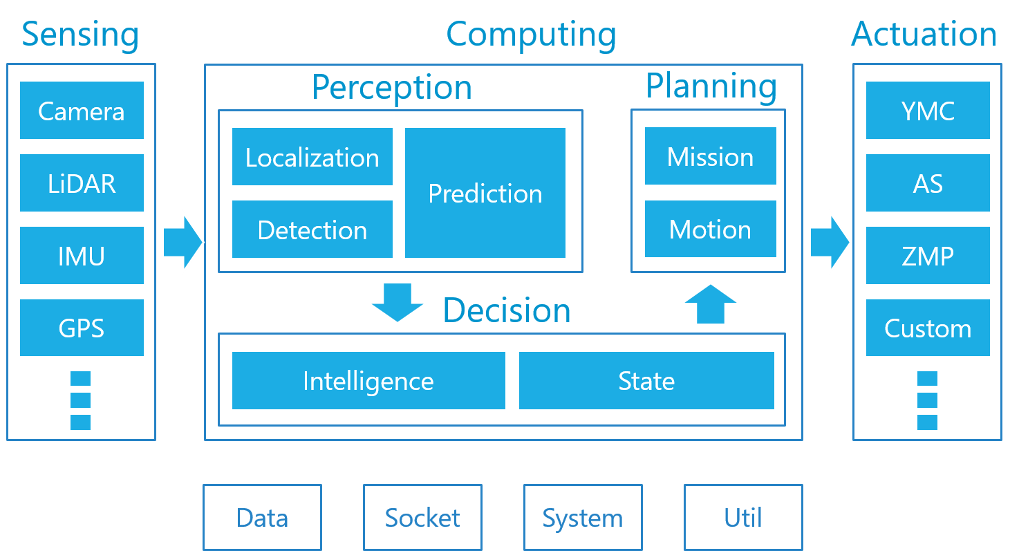
2. Computing/Perception(计算和感知)
Autoware 的感知能力由定位、检测和预测三部分组成。
- 定位是通过结合 GNSS 和 IMU 传感器的3D 地图和 SLAM 算法实现的。
- 检测使用摄像机和 LiDARs 传感器融合算法和深层神经网络。
- 预测是基于定位和检测的结果。 下面是由 Autoware 提供的突出显示的包和函数。
2.1. Localization(定位)
- lidar_localizer : 激光雷达定位器使用激光雷达扫描数据和预先构建的3D 地图信息,计算自我车辆在全局坐标系中的(x,y,z,roll,pitch,yaw)位置。 我们推荐使用正态分布变换(NDT)算法进行 LiDAR 扫描与三维地图的匹配,同时也支持迭代匹配(ICP)算法
- gnss_localizer :transforms the NMEA message from a GNSS receiver to the (x, y, z, roll, pitch, yaw) position. 该结果可以单独作为车辆的定位,也可以用于初始化和激光雷达定位器的定位结果进行融合互补
- dead_reckoner :该算法主要利用 IMU 传感器预测车辆的下一帧位置,并对激光雷达定位器和卫星定位器的定位结果进行插值处理。
2.2. Detection
- lidar_detector reads point cloud data from 3D laser scanners, and provides LiDAR-based object detection capabilities. The basic performance comes from the Euclidean Clustering algorithm, which finds clusters of the LiDAR scan (point cloud) above the ground. To classify the clusters, DNN-based algorithms are also supported, such as VoxelNet and LMNet.
- vision_detector reads image data from cameras, and provides image-based object detection capabilities. The main algorithms include R-CNN, SSD, and Yolo, which are designed to perform single DNNs for real-time performance. Multiple classes of detection are supported, such as cars and passengers.
- vision_tracker provides a tracking function for the results of vision_detector. The algorithm is based on Beyond Pixels. The results of tracking on an image plane are projected and combined with the result of lidar_detector in a 3D space through fusion_tools.
- fusion_detector reads both point cloud data from laser scanners and image data from cameras, and achieves further accurate object detection in a 3D space. The positions of laser scanner(s) and camera(s) must be calibrated in advance. The current implementation is based on the MV3D algorithm with a minor extension of the network as compared to the original algorithm.
- fusion_tools combines the results from lidar_detector and vision_tracker. The class information identified by vision_detector is added to the clusters of point cloud detected by lidar_detector.
- object_tracker predicts the motion of objects detected and identified by the above packages. The result of tracking can be further used for prediction of the object behavior and estimation of the object velocity. The tracking algorithm is based on the Kalman Filters. Another variant supports the Particle Filters as well.
2.3. Prediction
- object_predictor uses the result of object tracking described above to predict the future trajectories of moving objects, such as cars and passengers.
- collision_predictor uses the result of object_predictor to predict if the ego vehicle is involved in possible collision against the moving objects. The waypoint trajectory and the velocity information of the ego vehicle is also required as input data in addition to the result of object tracking.
- cutin_predictor uses the same pieces of information as collision_predictor to predict if neighbor cars cut in the front of the ego vehicle.
3. Computing/Decision
The decision module of Autoware bridges across the perception and the planning modules. Upon the result of perception, Autoware decides a driving behavior, represented by a finite state machine, so that an appropriate planning function can be selected. The current approach to decision making is a rule-based system.
3.1. Intelligence
- decision_maker subscribes a large set of topics related to the result of perception, map information, and the current state in order to publish the next-moment state topic. This state change will activate an appropriate planning function.
3.2. State
- state_machine changes the state within pre-defined rules, orchestrating with decision_maker.
4. Computing/Planning
The last piece of computing in Autoware is a planning module. The role of this module is to make plans of global mission and local (temporal) motion based on the results of the perception and the decision modules. A global mission is often determined when the ego vehicle starts or restarts, while a local motion is updated according to state changes. For example, the velocity of the ego vehicle is planned to become zero in front of an object with a safety margin or at a stop line if the state of Autoware is set to "stop". Another example is that the trajectory of the ego vehicle is planned to bypass an obstacle if the state of Autoware is set to "avoid". The primary packages included in the planning module are the following.
4.1. Mission
- route_planner searches for a global route to the destination. The route is represented by a set of intersections in the road network.
- lane_planner determines which lanes to be used along with the route published by route_planner. The lanes are represented by an array of waypoints, i.e., multiple waypoints, each of which corresponds to a single lane, are published by this package.
- waypoint_planner can be alternatively used to generate a set of waypoints to the destination. This package differs from lane_planner in that it publishes a single stroke of waypoints rather than an array of waypoints.
- waypoint_maker is a utility tool to save and load hand-made waypoints. To save waypoints to the specified file, you drive a vehicle manually while localization is activated, and Autoware records waypoints of the driving path with velocity information. The recorded waypoints can be loaded later on from the specified file to have the motion planning module subscribe them to follow that path.
4.2. Motion
- velocity_planner updates a velocity plan on the waypoints subscribed from either lane_planner, waypoints_planner, or *waypoints_maker** so as to speed down/up against surrounding vehicles and road features such as stop lines and traffic lights. Note that the velocity information embedded in the given waypoints is static, while this package updates a velocity plan according to driving scenes.
- astar_planner implements the Hybrid-State A* search algorithm that generates a feasible trajectory from the current position to the specified position. This package can be used for obstacle avoidance and sharp turns on the given waypoints as well as routing in free space such as parking lots.
- adas_lattice_planner implements the State Lattice planning algorithm that generates multiple feasible trajectories ahead of the current position based on spline curves, a pre-defined parameter table, and the ADAS Map (a.k.a., Vector Map) information. This package can be used mostly for obstacle avoidance and lane changes.
- waypoint_follower implements the Pure Pursuit algorithm that generates a twisted set of velocity and angular velocity (or just angle) to move the ego vehicle by uniform circular motion to a target waypoint over the given waypoints. This package should be used in combination with velocity_planner, astar_planner, and/or adas_lattice_planner. The published twisted set of velocity and angular velocity (or just angle) will be read by a vehicle controller or a by-wire interface, and finally the ego vehicle is controlled autonomously.
5. Actuation
Autoware has been installed and tested with a number of by-wired vehicles. Examples of "Powered by Autoware" are listed here.
The computational output of Autoware is a set of velocity, angular velocity, wheel angle, and curvature. These pieces of information are sent as commands to the by-wire controller through the vehicle interface. Controlling the steering and throttle needs to be taken care of by the by-wire controller.