1. 运行官方Demo
1.1. 下载数据集
1 | wget -P ~/Downloads https://storage.googleapis.com/cartographer-public-data/bags/backpack_2d/cartographer_paper_deutsches_museum.bag |
使用rosbag回放一下数据集,检查有哪些传感器:
1 | msi@msi:~/carto/carto_ros/data$ rostopic list |
可以看到,数据集仅仅包含imu传感器,两个激光雷达(水平+垂直放置),没有里程计,也没有TF变换。
疑惑:那么,IMU、激光雷达与机器人本体base_link之间的相对位置关系是在哪里确定的呢?[代码中sensorBridge需要将传感器的数据转换到机器人本体坐标系下,那么就需要这些相对位置关系]
答:在carto_ros/src/cartographer_ros/cartographer_ros/urdf/ 文件夹中,有一个backpack_2d.urdf,里面定义了机器人本体与各个传感器之间的相对位置关系,同时,在启动文件中,可以找到如下两行:
1 | <param name="robot_description" |
这两行定义了机器人的模型,同时发布了机器人模型中的各个相对坐标关系,在下面的Demo运行中,可以看到由robot_state_publisher节点读取backpack_2d.urdf模型然后发布的TF变换。
1.2. 运行官方给出的Demo启动文件
1 | source ./install/setup.bash |
1.3. rqt查看节点关系和TF变换
1.3.1. 节点关系
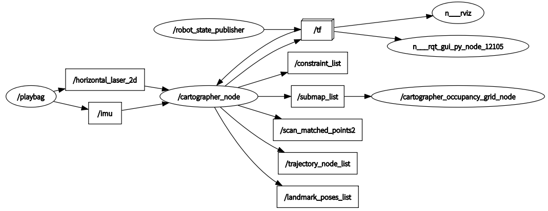
1.3.2. TF变换(由backpack_2d.urdf模型定义)
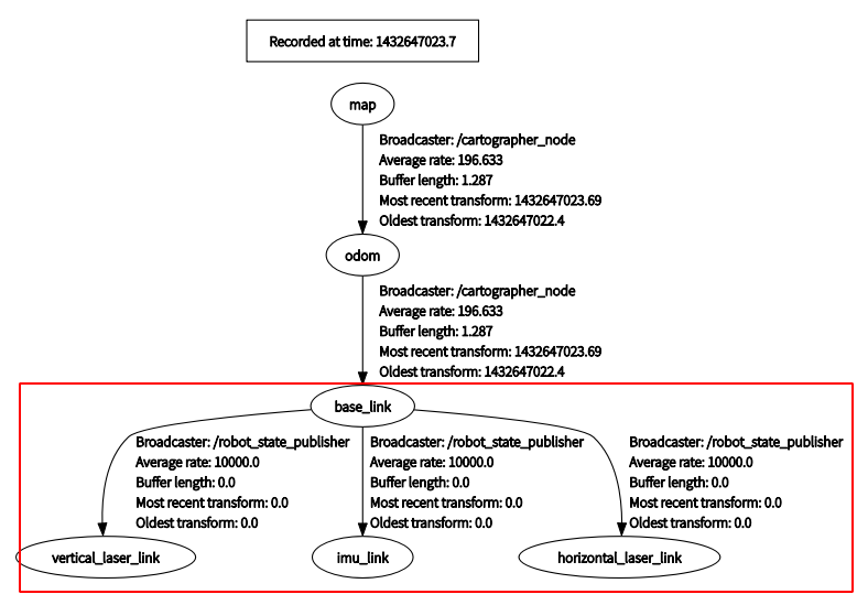
可以看到,红色框标注的地方,就是由robot_state_publisher节点读取backpack_2d.urdf模型然后发布的TF变换。上面的部分则是由cartographer节点定位所发布的map-->odom的TF变换。
传感器与机器人本体之间的TF变换对于运行cartographer来说是十分重要的,如果没有这些相对坐标关系,cartographer将无法运行。
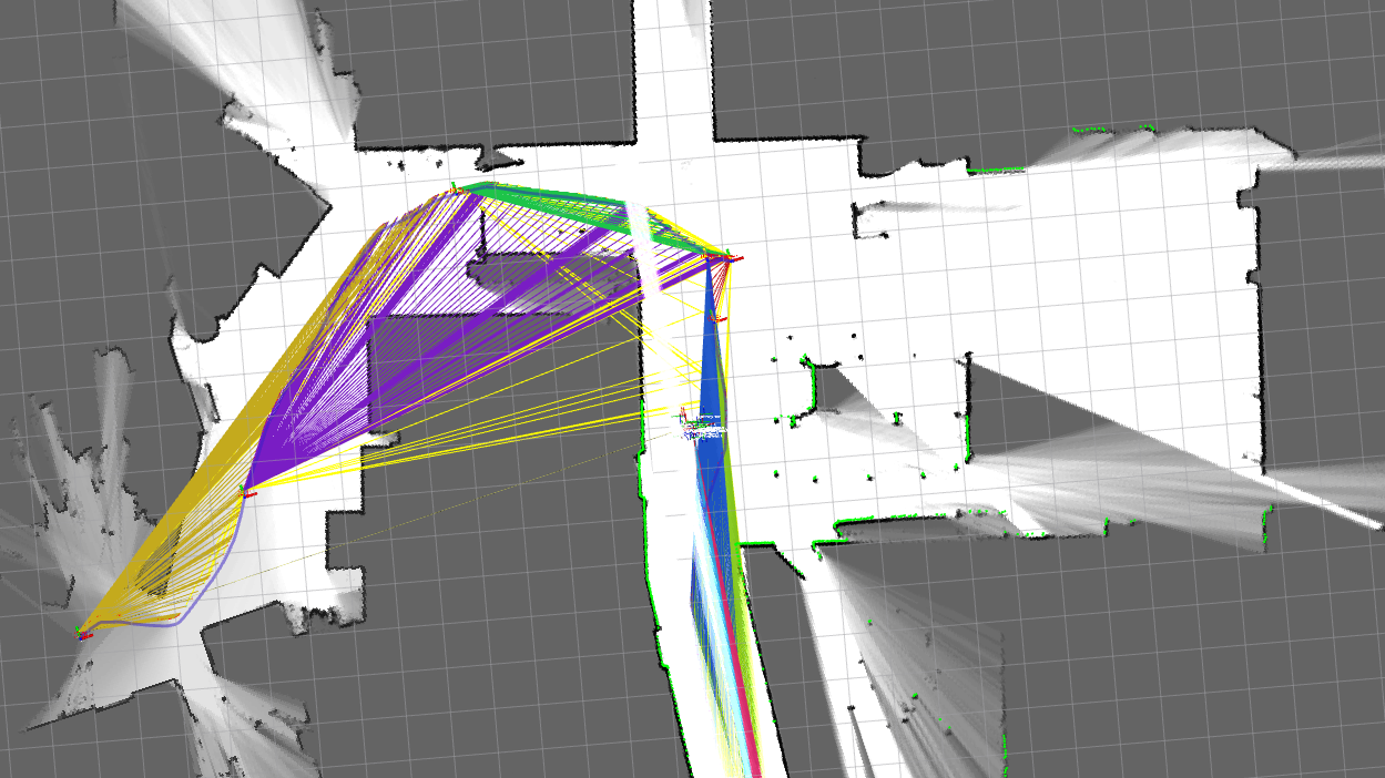
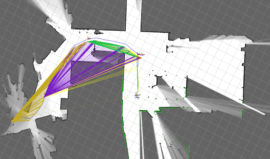
1.4. 运行效果
初始启动:
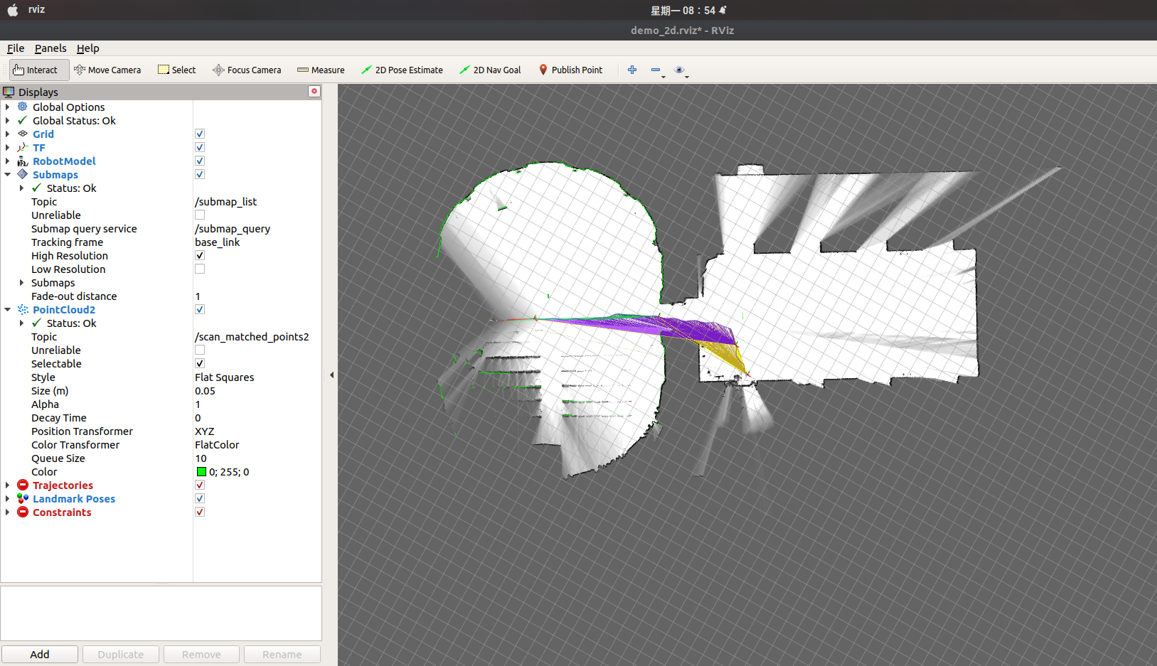
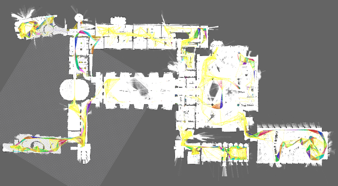
最终完成:
1.5. 总结
从最终的效果来看,官方Demo的效果(建图和跟踪)都比传统的滤波方法好很多,另外,在这个数据集中,仅有激光雷达和IMU,连里程计都没有使用,这说明了程序对这个数据集做了很多的适配工作。为了验证cartographer对其他数据集是否具有普适性,接下来将使用MIT数据集进行测试。
2. 运行MIT数据集
数据集官方地址:mit stata center data set
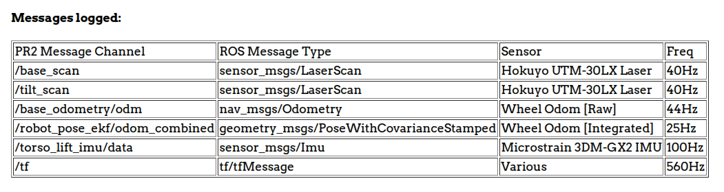
从官方给出的数据集详细来看,有这些传感器TOpic
- /base_scan: 水平放置的激光雷达
- /tilt_scan: 倾斜放置的激光雷达
- /base_odometry/odom: 里程计
- /robot_pose_ekf/odom_combined: 使用EFK滤波得到的里程计数据(可能是里程计+IMU融合)
- /torso_lift_imu/data: IMU数据
- /tf: 传感器相对位置?
- ...
2.1. 下载数据集
这个数据集有点坑的地方就是,它的机器人是会坐电梯在楼层之间跑的,因此需要选择一个只在一个平面上跑的数据集。
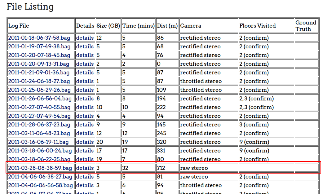
1 | wget http://infinity.csail.mit.edu/data/2011/2011-03-28-08-38-59.bag |
使用rosbag回放,检查数据集内容:
TF变换信息
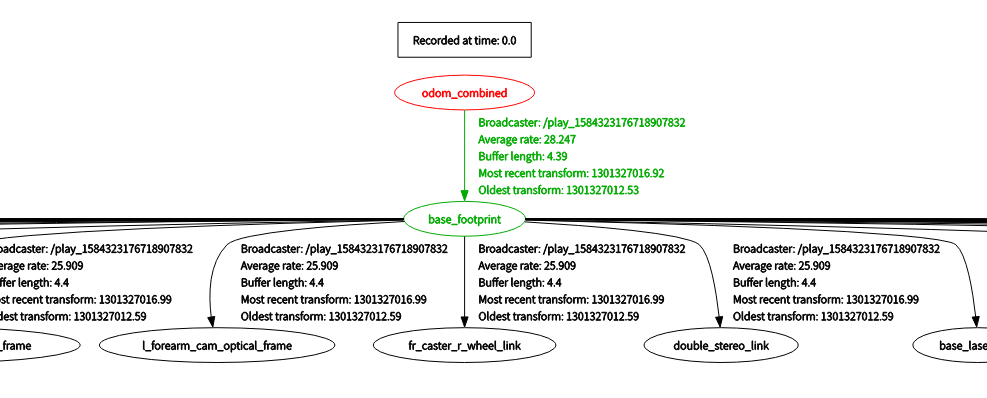
从TF变换树可以看到,这里的里程计信息是采用经过EKF滤波之后的里程计坐标系
odom_combined,而不是直接的odom。
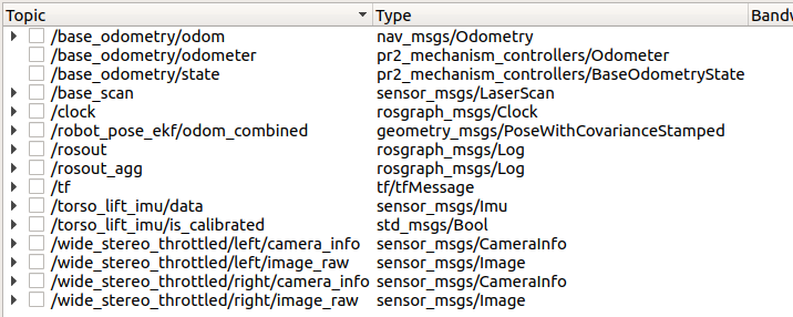
传感器话题
2.2. 使用IMU+激光扫描,运行cartographer
2.2.1. 配置文件适配
(1).launch启动文件
在运行之前,需要对配置文件进行修改,因为数据集的传感器Topic与官方Demo的不一样,主要是IMU和激光扫描的Topic
对backpack_2d.launch文件进行修改:
修改之后的内容如下:
- 移除了
robot_state_publisher节点以及urdf机器人模型 : 这是因为在数据集中已经提供了传感器与机器人本体的相对位置关系 - 传感器Topic的重映射: 将数据集中的激光扫描"base_scan"映射为"scan",将IMU话题"torso_lift_imu/data"映射为"imu"
- 指定参数配置文件为
my_script_backpack_2d.lua
my_script_backpack_2d.launch
1 | <launch> |
(2).lua参数配置文件
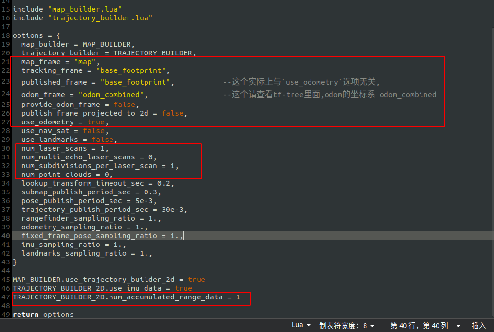
因为数据集的TF变换中,机器人本体坐标系不是base_link,而是base_footprint,因此需要修改。
对backpack_2d.lua文件进行修改,然后保存为my_script_backpack_2d.lua,主要修改内容:
- 修改"tracking_frame",为"base_footprint"
- 修改"published_frame",为"base_footprint"
- 修改"num_laser_scans",为1 (这是因为数据集中的激光扫描是LaserScan消息类型)
- 修改"num_multi_echo_laser_scans","num_point_clouds",均为0
my_script_backpack_2d.lua:
1 | include "map_builder.lua" |
2.2.2. 启动cartographer
(修改完配置文件之后,需要重新编译一下,否则修改无效)
1 | source ./install/setup.bash |
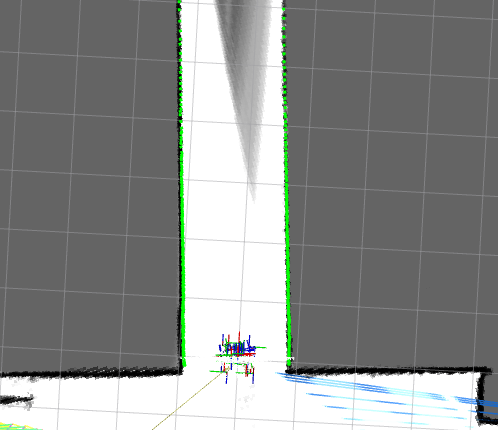
2.2.3. 运行效果
初始启动
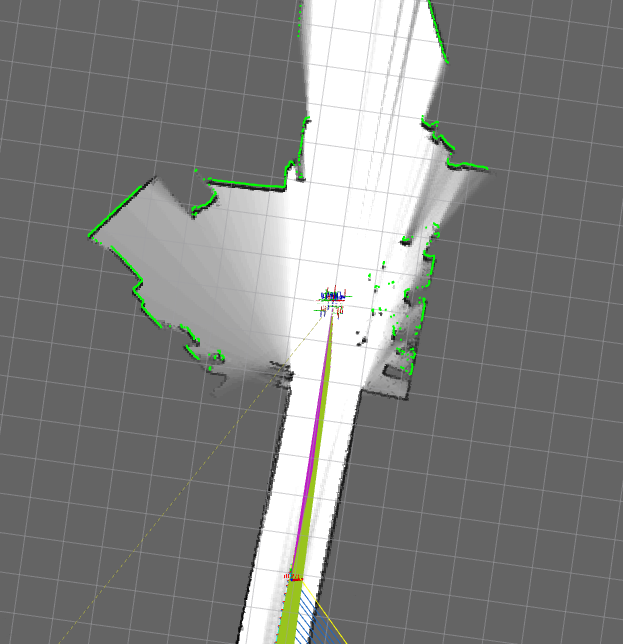
遇到长直走廊:
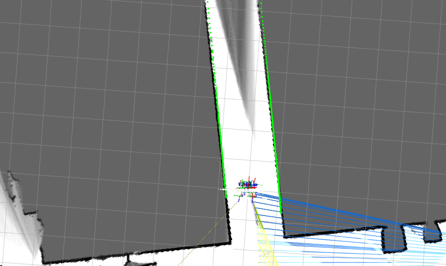
在走廊中定位错误,导致建图重叠:
2.2.4. 总结
单纯使用IMU+激光扫描时,在特征良好的环境下定位、建图效果都不错,但是遇到长直走廊,就出现定位失败的问题,使得建图也出现错误。这种情况下,下面尝试把里程计也融合进去,再看效果如何。
2.3. 使用IMU+里程计+激光扫描,运行cartographer
2.3.1. 配置文件适配
(1).launch启动文件,需要对里程计topic进行重映射
1 | <remap from="odom" to="base_odometry/odom" /> |
(2).lua参数配置文件
重点
由于数据集包含的TF变换中,里程计的坐标系是odom_combined而不是odom,(可以往回看看),因此需要修改。
在上面的IMU尝试的基础上,继续my_script_backpack_2d.lua文件进行修改,主要修改内容:
- 修改"odom_frame",为"odom_combined"
- 修改"provide_odom_frame",改成
false,因为数据集已经提供了里程计的坐标系了 - 修改"use_odometry",为
true
修改之后的my_script_backpack_2d.lua完整内容:
1 | include "map_builder.lua" |
2.3.2. 启动cartographer
(修改完配置文件之后,需要重新编译一下,否则修改无效)
1 | source ./install/setup.bash |
出现报错
1 | at line 126 in /tmp/binarydeb/ros-melodic-tf2-0.6.5/src/buffer_core.cpp |
出现这个错误,实际上是因为这个MIT数据集的里程计消息不完整
2.3.3. 错误检查
检查里程计消息:
1 | rostopic echo /base_odometry/odom |
得到如下:
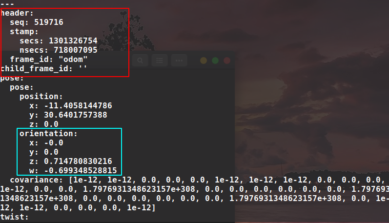
- 问题出现在红色框部分: odom消息的
child_frame_id居然为空,正常的里程计消息中,child_frame_id一般为base_link,用来指定这是哪个坐标系相对于里程计坐标系的里程信息。 - 蓝色框部分是需要注意的地方,cartographer要求里程计信息带有四元数旋转信息,这个数据集有,是可以的。
2.3.4. 进一步适配
现在知道了错误所在,那么接下来就是对里程计信息进行修正。
从数据集的TF变换:
可以看到,这里的里程计坐标系是采用经过EKF滤波之后的里程计坐标系odom_combined,而不是直接的odom。
那么干脆使用经过EKF滤波之后融合里程计/robot_pose_ekf/odom_combined好了,但是问题来了,这个msg的消息类型是geometry_msgs/PoseWithCovarianceStamped而不是nav_msgs/Odometry
接下来需要编写一个节点,订阅/robot_pose_ekf/odom_combined这个Topic,然后发布nav_msgs/Odometry类型的里程msg
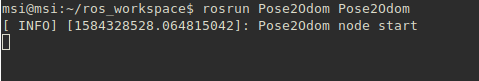
这个节点我已经写好了
Pose2Odom.cpp
1 |
|
这个节点的主要功能是:
- 订阅"/robot_pose_ekf/odom_combined",然后转换成"nav_msgs::Odometry"消息类型
- 同时,设置
child_frame_id为:base_footprint
2.3.5. 再次启动cartographer
(1)把.launch里面的关于里程计的reamap去掉,因为上面的节点直接发布Topic为odom的消息,就不需要重映射了。
(2)启动上面的Pose2Odom节点
(3)启动cartographer
1 | source ./install/setup.bash |
2.3.6. 运行效果
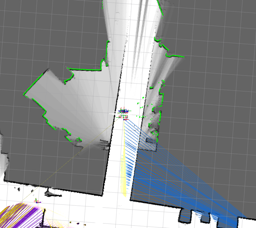
初始运行(可以正常启动了)
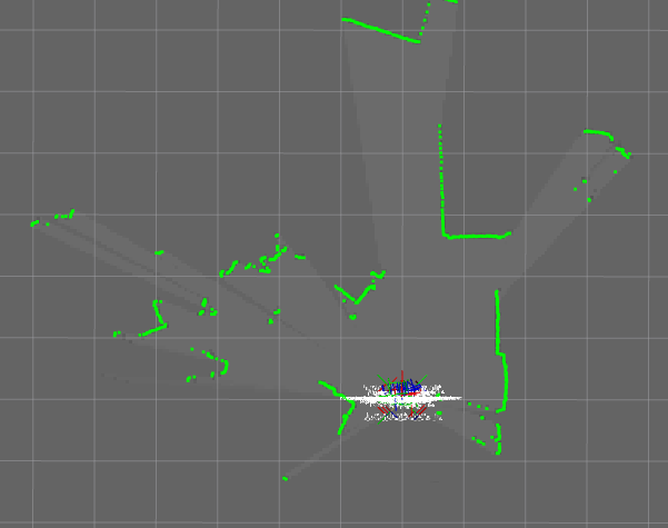
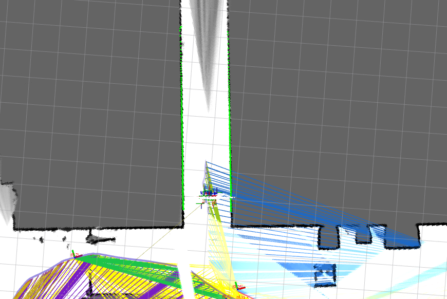
再次遇到长直走廊
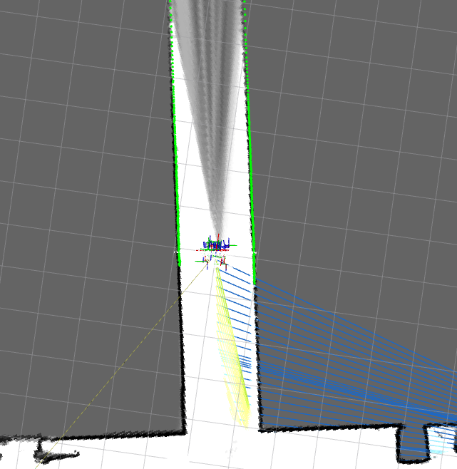
没有出现地图重叠的情况了
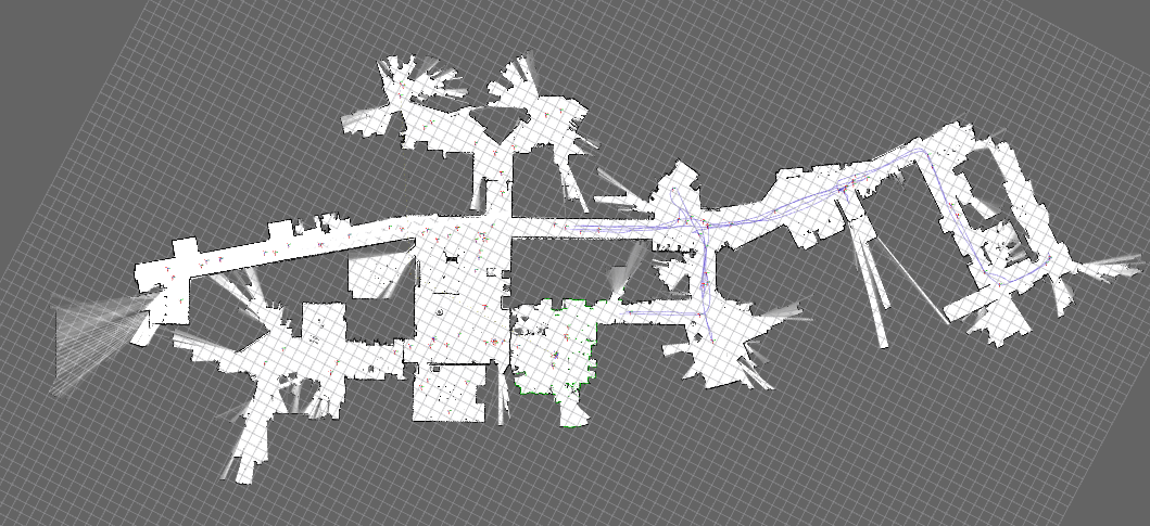
最终建立完整的地图:
2.4. 总结
通过使用MIT数据集进行测试,可以发现,cartographer具有一定的普适性,但是对于长直走廊时的建图和定位,cartographer其实是会受到影响的,单纯使用IMU+激光扫描会出现定位失败,从而导致建图错误的情况,融合里程计之后,情况有所改善(这是因为cartographer里面关于位姿图的优化问题中添加了里程计残差项作为约束),同时里程计也为姿态外推器(航迹推算)提供了比较好的先验信息(因为在较短时间内,里程计数据可看作是准确的)。
3. 一些思考
3.1. cartographer已经实现的
(1)定位方式有3种
- correlative_scan_matching: ~公司采用的
- fast_correlative_scan_matching: 分枝定界加速相关性匹配
- ceres_scan_matching: 非线性优化位姿
(2)图优化理论
Pose_Graph: 位姿图
顶点:
- 子图全局位姿
- 节点全局位姿
约束项(残差项):
- 节点与当前子图的
correlative_scan_matching可产生一个节点--子图约束 - 节点与所有子图的
fast_correlative_scan_matching可产生多个节点--子图约束(即回环检测,如果回环匹配上了,则可构成约束) - 节点之间的里程计信息产生
节点--节点约束 - 节点之间的局部SLAM( local SLAM: 即节点与子图
correlative_scan_matching得到节点在local map的位姿)可构成节点--节点约束[利用两个节点的local map位姿产生] - 路标点,产生
路标--节点的约束? (这一块代码还没详细阅读)
3.2. cartographer还没有实现的
- GPS数据的融合(用于重定位、检测回环、产生约束)
- 重定位功能
- 视觉信息的融合
3.3. 可以有突破点的地方
- 基于路标的长直走廊定位(基于视觉的路标信息)
- 重定位
- GPS融合